MIDIbox CV V1
NOTE: This design is expired! In 2012..2014 MIDIbox CV V2 has been developed which replaced the old version. See this page for more details.
 Feature list: Feature list:
- requires CORE and AOUT or AOUT_LC or AOUT_NG module
- up to 8 CV outputs with 12 bit resolution
- 8 gate outputs
- Outputs can be assigned to 16 MIDI Channels and Note/Velocity/Aftertouch/CC/NRPN/Pitchbender events
- 8 independent Note stacks with 16 notes depth!
- Mono/Legato/8*Poly mode
- selectable Pitchbender range
- Octave and Semitones Transpose function
- Keyboard Split/Layer function
- Selectable Gate Polarity
- Selectable Output Curve: V/Oct, Hz/V, Inverted, Exponential
- Interpolation function (smoother) with selectable slew rate from (1mS..64mS)
- DIN Sync Output (StartStop and Clock) with various dividers and multipliers (96ppqn .. 24ppqn / 16)
- Easy to use Calibration Function
- MIDI Merger (MIDIbox Link compatible)
- support for BankStick, stores 128 patches
- configuration via 4 buttons/LCD or via SysEx
Hardware Options -
Following options have to be considered when you are planning your MIDIbox CV:
- MBHP_AOUT, MBHP_AOUT_LC or MBHP_AOUT_NG module: either one MBHP_AOUT or up to 4xMBHP_AOUT_LC or one MBHP_AOUT_NG module can be handled by a single MIDIbox CV.
- MBHP_AOUT: high quality interface with eight 12-bit CV outputs. Two MAX525 are required, these DACs are very expensive (each chip ca. 30 EUR!).
Interconnections to MBHP_AOUT module
- MBHP_AOUT_LC: low-cost interface with two CV outputs, either 12-bit/8-bit or 8-bit/8-bit configuration. Four MBHP_AOUT_LC modules can be chained in order to get eight outputs. This interface is really cheap, but it takes some time to build the module due to the high number of resistors.
Interconnections to MBHP_AOUT_LC module
- MBHP_AOUT_NG: high quality interface with eight 12-bit CV outputs. One TLV5630 is required - best value! (US $15)
Interconnections to MBHP_AOUT_NG module
- Alternative DACs could also be handled by MIDIbox CV, but this requires a driver adaption. The drivers can be found in cv_aout.inc and cv_aout_lc.inc
- 2x16 LCD: the most comfortable solution to configure the MIDIbox CV is by using the menu interface. At least for debugging it makes sense to spent the core a LCD (a 2x16 backlit LCD is available for 7.50 EUR at Reichelt), therefore the usage without a LCD/menu hasn't been focused during the development. The configuration can be changed from a PC via SysEx, but an editor is not available (yet). Therefore please consider to build the menu interface!
- DINX1: a shift register is required for the 4 menu buttons (resp. the two menu buttons + the datawheel, see below). It doesn't make sense to build a complete DINX4 module just for 4 digital inputs, therefore I suggest to build a single 74HC165 shift registers + 9*10k resistors on the same veroboard where your buttons are mounted.
- 4 buttons or 2 buttons/datawheel: the menu navigation requires at least one Exit and one Select button. For data entry either Inc/Dec Buttons, or a datawheel (rotary encoder) can be used.
Interconnection diagram for 4 button configuration
Interconnection diagram for 2 buttons and one datawheel configuration
- BankStick: a 24LC256 BankStick is recommended, it allows you to store 128 patches. Patches can be named for best oversight. Multiple BankSticks are not supported, but the stick is hot-swappable.
Hardware Configuration Since MIDIbox CV supports so many different hardware options, it is evtl. required to customize the firmware. The basic setup which will propably never be altered cannot be edited from the menu interface, instead it has to be changed in the setup_*.asm file of the application.
- Buttons and optional datawheel
- 4 Buttons: thats the default setup which doesn't need to be changed if you are planning to use it. Following defines in setup_*.asm select the pin numbers of the "DINX1" module:
#define DEFAULT_DIN_MENU_EXEC         7
#define DEFAULT_DIN_MENU_RIGHT        6
#define DEFAULT_DIN_MENU_LEFT         5
#define DEFAULT_DIN_MENU_SELECT       4
- 2 Buttons and one datawheel: DEFAULT_ENC_DATAWHEEL must be set to 0 in order to select the first encoder. The encoder connections are specified in mios_tables.inc, the Exec and Select pin number in setup_*.asm
;; mios_tables.inc:
;;        SR  Pin  Mode
ENC_ENTRY  1,  4,  MIOS_ENC_MODE_DETENTED       ; Data Wheel
;;       (and  5)

;; setup_*.asm:
#define DEFAULT_DIN_MENU_EXEC         7
#define DEFAULT_DIN_MENU_SELECT       6
- Gate Outputs: if a MBHP_AOUT module is used, two gate outputs are provided by the module itself, they are assigned to CV1 and CV2. The remaining outputs are available directly at the J5 socket of the core module. This is the only option for the MBHP_AOUT_LC and MBHP_AOUT_NG module (there is no disadvantage!).
Note that the gate outputs at J5 are not enabled by default. This is to reduce the risk that somebody doesn't read the documentation and uploads the firmware on a MIDIbox64 (or similar), where J5 is used as pot input. A short circuit would happen which could destroy the port drivers.
Therefore J5 has to be enabled explicitely in setup_*.asm:
; use PORTA and PORTE (J5 of the core module) for 8 additional gate outputs
#define ENABLE_J5 0
- AOUT interface: it has to be specified, if a common MBHP_AOUT, MBHP_AOUT_LC or MBHP_AOUT_NG module is connected to the core:
;   1: one MBHP_AOUT module
;   2: up to 4 (chained) MBHP_AOUT_LC modules
;   3: one MBHP_AOUT_NG module
#define DEFAULT_AOUT_INTERFACE 1
- If one or more MBHP_AOUT_LC modules are used, the resolution configuration has to be specified in addition:
;   1: first CV output 12bit, second CV output 4bit
;   2: first CV output 8bit, second CV output 8bit
#define DEFAULT_AOUT_LC_1_RESOLUTION 1  ; 1st AOUT_LC module
#define DEFAULT_AOUT_LC_2_RESOLUTION 1  ; 2nd AOUT_LC module
#define DEFAULT_AOUT_LC_3_RESOLUTION 1  ; 3rd AOUT_LC module
#define DEFAULT_AOUT_LC_4_RESOLUTION 1  ; 4th AOUT_LC module
- The sync clock output is available at pin RC0 of the PIC (port J6:SC of the core module) by default, the pin can be changed if desired:
#define DEFAULT_EXT_CLK_LAT            LATC
#define DEFAULT_EXT_CLK_PIN            0
- The sync start/stop output is available at pin RC1 of the PIC (port J6:RC of the core module) by default, the pin can be changed if desired:
#define DEFAULT_EXT_START_STOP_LAT     LATC
#define DEFAULT_EXT_START_STOP_PIN     1
- Also the pulsewidth of the clock output can be configured in pieces of 500 uS. By default it's 1 mS:
; 0 -> 500 uS
; 1 -> 1   mS
; 2 -> 1.5 mS
; etc...
#define DEFAULT_EXT_CLK_PULSEWIDTH 1
- The Chip Select number of the BankStick which is used by MBCV can be defined:
; 0: disables BankStick, 1..8: selects CS#0..CS#7
; If you are unsure about the right value, use 1 (for CS#0, all CS inputs
; tied to ground), even when no BankStick is connected
; ("hotplug", will be detected automatically)
#define DEFAULT_BANKSTICK_NUMBER 1
- The MIDI channel for patch changes can be defined here:
; 0: patches can only be changed from CS, 1-16: MIDI channel for program changes
#define DEFAULT_PATCH_CHANGE_CHANNEL 1
- Once all changes have been made, the application has to be rebuilt like described at this HowTo page.
Menus -
The purpose of the buttons/datawheel:
- EXIT: use this button to exit the current menu page
- SELECT: in most menus this button is used to select the parameter (cursor position)
- LEFT/RIGHT or Datawheel: increments/decrements the selected parameter
And here a description about the available menu pages:

Main Page |
 This is the initial screen after power-on. It consists of the patch number, 8 meters which display the CV output value and which show animated triggers when the value is changed via MIDI. At the bottom line the patch name is displayed. This is the initial screen after power-on. It consists of the patch number, 8 meters which display the CV output value and which show animated triggers when the value is changed via MIDI. At the bottom line the patch name is displayed.
The patch number P001..P128 can be changed within this page by pressing the left/right button/turning the datawheel.
 Changes in the configuration can be stored within this page by pressing the SELECT button for more than 2 seconds. Changes in the configuration can be stored within this page by pressing the SELECT button for more than 2 seconds.
 You will be asked for the patch destination. Note that the lower line displays the name of the patch which will be overwritten! You will be asked for the patch destination. Note that the lower line displays the name of the patch which will be overwritten!
Press SELECT again to continue with the next page, otherwise press EXIT to abort the saving process.
 You will be asked for the new patch name. Press SELECT to move the cursor to the next character. SELECT has to be pressed 17 times (16 characters + confirmation) to finally store the configuration. Note that also in this page the process can be aborted by pressing the EXIT button. You will be asked for the new patch name. Press SELECT to move the cursor to the next character. SELECT has to be pressed 17 times (16 characters + confirmation) to finally store the configuration. Note that also in this page the process can be aborted by pressing the EXIT button.
|

MIDI Events |
 In most menus you can select the CV output and other parameters. In most menus you can select the CV output and other parameters.
 The cursor position can be changed with the SELECT button. The cursor position can be changed with the SELECT button.
 In this submenu the incoming MIDI events can be assigned to the 8 CV outputs. With "Note" the appr. CV output will change its voltage level on incoming Notes (1V/octave). In this submenu the incoming MIDI events can be assigned to the 8 CV outputs. With "Note" the appr. CV output will change its voltage level on incoming Notes (1V/octave).
In addition, the voltage level can be shifted with the PitchBender depending on the selected Pitchbender Range (-> see Pitchrange menu). Each CV output has it's own note stack (-> see Note Handling menu).
 With "Vel." the voltage level changes with the velocity of the Note. With "Vel." the voltage level changes with the velocity of the Note.
 With "ATch." the voltage level changes with incoming Aftertouch events. With "ATch." the voltage level changes with incoming Aftertouch events.
 With "CC" the voltage level is changed with incoming MIDI controller events. The CC number has to be selected separately in the "CC/NRPN number" submenu. With "CC" the voltage level is changed with incoming MIDI controller events. The CC number has to be selected separately in the "CC/NRPN number" submenu.
 With "NRPN" the voltage level is changed with incoming NRPN events. This is a special CC format which transfers a value in 14-bit resolution. The NRPN LSB number (CC#98) has to be selected separately in the "CC/NRPN number" submenu. The MSB (CC#99) is always 0. The MSB data is transfered with CC#6, the LSB data with CC#38. With "NRPN" the voltage level is changed with incoming NRPN events. This is a special CC format which transfers a value in 14-bit resolution. The NRPN LSB number (CC#98) has to be selected separately in the "CC/NRPN number" submenu. The MSB (CC#99) is always 0. The MSB data is transfered with CC#6, the LSB data with CC#38.
 With "PitchBender" the voltage level is changed with incoming PitchBender events. With "PitchBender" the voltage level is changed with incoming PitchBender events.
|

Transpose |
 CV output which are assigned to Notes can be transposed individually by -8/+7 octaves and -8/+7 semitones. CV output which are assigned to Notes can be transposed individually by -8/+7 octaves and -8/+7 semitones.
|

Keyboard Zone |
 CV outputs which are assigned to Notes can be split into different keyboard zones. This allows you to play different sounds with a single keyboard. You are also able to layer sounds by overlapping the zones and transposing the notes. CV outputs which are assigned to Notes can be split into different keyboard zones. This allows you to play different sounds with a single keyboard. You are also able to layer sounds by overlapping the zones and transposing the notes.
|

Pitchrange |
 CV outputs which are assigned to Notes can be controlled with a Pitchbender in addition. This submenu allows you to define about how many semitones the Pitchbender should shift the voltage level in negative and positive direction. CV outputs which are assigned to Notes can be controlled with a Pitchbender in addition. This submenu allows you to define about how many semitones the Pitchbender should shift the voltage level in negative and positive direction.
|

Note Handling |
MIDIbox CV provides an individual note stack for each CV output. A note stack is not only advantageous for poly, but only for mono synths, because it improves live playing - without a note stack the Legato/Mono mode couldn't determine the held keys:
 Legato means that the gate will be switched on with the first pressed key, and it will be switched off when all keys are released. Legato means that the gate will be switched on with the first pressed key, and it will be switched off when all keys are released.
 Mono means that the gate will be re-triggered if a new key is pressed or if a key is released while other keys are still held. Mono means that the gate will be re-triggered if a new key is pressed or if a key is released while other keys are still held.
 Poly assigns all played keys to different CV outputs. The first note will always be forwarded to CV output #1, the second to #2, to third to #3 and so on if the appr. outputs are assigned to Notes in the MIDI event menu. This means, that you are still able to use the last outputs for other MIDI events. Poly assigns all played keys to different CV outputs. The first note will always be forwarded to CV output #1, the second to #2, to third to #3 and so on if the appr. outputs are assigned to Notes in the MIDI event menu. This means, that you are still able to use the last outputs for other MIDI events.
|

CC/NRPN Number |
 In this submenu the CC or NRPN LSB number has to be selected which is used when the appr. output reacts on CC or NRPN events. In this submenu the CC or NRPN LSB number has to be selected which is used when the appr. output reacts on CC or NRPN events.
|

Gate Polarity |
 the polarity of each individual gate output can be changed in this menu page. We have positive gate outputs by default (Gate goes high when a key is pressed). the polarity of each individual gate output can be changed in this menu page. We have positive gate outputs by default (Gate goes high when a key is pressed).
 By changing the polarity, the gate will be inverted (gate goes low when a key is pressed). By changing the polarity, the gate will be inverted (gate goes low when a key is pressed).
|

Output Curve |
 The output curve for each individual CV output can be changed in this menu page. 1V/Oct is a linear curve which is provided by most synthesizers. The output curve for each individual CV output can be changed in this menu page. 1V/Oct is a linear curve which is provided by most synthesizers.
 The V/Hz scaling is suitable for synths like the Korg MS-20. Note that this output behaviour needs to be calibrated, the calibration process is described below. The V/Hz scaling is suitable for synths like the Korg MS-20. Note that this output behaviour needs to be calibrated, the calibration process is described below.
 Optionally the linear output curve can be inverted if desired. Optionally the linear output curve can be inverted if desired.
 An exponential curve is also available, this could be helpful if a CV output is assigned to velocity. An exponential curve is also available, this could be helpful if a CV output is assigned to velocity.
|

Interpolation |
 The interpolation function allows you to smooth the CV output with a selectable slew rate from 1mS to 64mS (in steps of 2^n). The interpolation function allows you to smooth the CV output with a selectable slew rate from 1mS to 64mS (in steps of 2^n).
This feature is especially useful when CV outputs are controlled by 7bit velocity or CC values, as it gets use of the full 12bit resolution and reduces zipper noise dramatically.
Demo:
mbcv_without_interpolation.mp3
CC filter sweep without interpolation
mbcv_with_interpolation.mp3
CC filter sweep with interpolation
|

Clock Divider |
 A clock sync output is available at J14 of the core module which is triggered on each incoming MIDI clock. The MIDI clock has a resolution of 24ppqn (24 pulses per quarter note). A clock sync output is available at J14 of the core module which is triggered on each incoming MIDI clock. The MIDI clock has a resolution of 24ppqn (24 pulses per quarter note).
 Optionally the resolution of the clock can be increased by 32, 48 or 96 ppqn. This is realized by using a software implemented "phase locked loop" (PLL). Optionally the resolution of the clock can be increased by 32, 48 or 96 ppqn. This is realized by using a software implemented "phase locked loop" (PLL).
 The 24ppqn MIDI clock can also be divided by 1, 2, 3, 4, 5, ... 16 if desired. The 24ppqn MIDI clock can also be divided by 1, 2, 3, 4, 5, ... 16 if desired.
|

Calibration |
 This menu page simplifies the calibration of the AOUT module. This menu page simplifies the calibration of the AOUT module.
 Different voltages can be selected (Minimum, Middle, Maximum, 1.00V, 2.00V, 4.00V and 8.00V), which have to be measured at the CV output. Different voltages can be selected (Minimum, Middle, Maximum, 1.00V, 2.00V, 4.00V and 8.00V), which have to be measured at the CV output.
 If the output values don't match, they can be adjusted on the gain and offset trimmers. If the output values don't match, they can be adjusted on the gain and offset trimmers.
 The calibration process is described below. It should be mentioned here, that calibration is especially required when you are switching between the 1V/Oct to the Hz/V output curve characteristic. The calibration process is described below. It should be mentioned here, that calibration is especially required when you are switching between the 1V/Oct to the Hz/V output curve characteristic.
|

MIDI Configuration |
 The MIDI merger allows you to plug the MIDIbox and a keyboard to a computer w/o the need for a second MIDI In interface. Just plug the MIDI Out of your keyboard to the MIDI In of MIDIbox and the MIDI Out of the MIDIbox to the MIDI In of your computer. The MIDI merger allows you to plug the MIDIbox and a keyboard to a computer w/o the need for a second MIDI In interface. Just plug the MIDI Out of your keyboard to the MIDI In of MIDIbox and the MIDI Out of the MIDIbox to the MIDI In of your computer.
 If you connect the MIDI In of the MIDIbox with MIDI Out of your computer, you should disable the MIDI merger in order to avoid endless feedback loops. If you connect the MIDI In of the MIDIbox with MIDI Out of your computer, you should disable the MIDI merger in order to avoid endless feedback loops.
 If multiple MIDIboxes should be cascaded based on the MIDIbox Link concept, all MIDIboxes have to be declared as MIDIbox Link Forwarding Point... If multiple MIDIboxes should be cascaded based on the MIDIbox Link concept, all MIDIboxes have to be declared as MIDIbox Link Forwarding Point...
 except for the last MIDIbox which has to be declared as MIDIbox Link Endpoint. except for the last MIDIbox which has to be declared as MIDIbox Link Endpoint.
 Note: In this menu, you are also able to enable the MIDIbox-to-COM option with the SELECT button. Find more informations at the MIDIbox-to-COM Interface Page! Note: In this menu, you are also able to enable the MIDIbox-to-COM option with the SELECT button. Find more informations at the MIDIbox-to-COM Interface Page!
|

Send SysEx |
 In this submenu the device ID can be selected, and a SysEx dump which contains the current configuration can be triggered manually with the SELECT button. In this submenu the device ID can be selected, and a SysEx dump which contains the current configuration can be triggered manually with the SELECT button.
Note that the device ID won't be saved in the EEPROM memory, it will be derived from the MIOS device ID after power-on.
|
Calibration -
The CV outputs can be easily calibrated from the Calibration menu page. You need a multimeter to measure the output levels, with digital multimeters it's easier than with analog multimeters. Note that especially cheap multimeters could have a tolerance of 0.5% and more, which means, that if you measure 8.00V, the real voltage level could be in between 8.04V and 7.96V. Especially AOUT_LC users will notice an additional linearity error which is caused by not perfectly matching values of the 10k resistors. Therefore don't consume too much time to get perfectly matching levels, try to find the best fitting values!
- 1V/Octave: the maximum voltage should be 10.67V. This value is derived from the available number of notes (128): 10.67V / 128 = 0.0834V, an octave consists of 12 semitones -> 12*0.0834V = 1.00V
MBHP_AOUT_LC users have to calibrate the offset first: select "Min.", and adjust the offset trimpot until the CV out reaches 0.00V
Thereafter select "Max." and adjust the gain trimpot until the voltage reaches ca. 10.67V
Now doublecheck the gain: select 1.00V, 2.00V, 4.00V and 8.00V and adjust the gain until the selected values are reached as good as possible.
- Hz/V: the maximum voltage should be 10.24V. This value has been choosen to simplify the calculation of the required voltage levels for each note. With 10.24V and 12bit resolution, each DAC step can increase the voltage by 0.005V.
Important: first go into the "Output Curve" page and select "Hz/V", otherwise you will measure the wrong results. This curve has to be selected for each CV separately which should use this characteristic.
Thereafter go into the calibration menu, adjust the offset (if required), select the maximum voltage, adjust the gain until 10.24V is reached, then try 1.00V, 2.00V, 4.00V and 8.00V
- Bipolar voltages (e.g. -5V/+5V): some synths require a bipolar voltage to control sound parameters like Finetune, ADSR, CutOff/Resonance, etc.
Users of a MBHP_AOUT module need to add the Balanced CV extension to each output in order to get the possibility for adjusting the output voltage below 0V
An offset trimpot is already available on the AOUT_LC and AOUT_NGmodule.
In order to calibrate the balanced CV, first select "Middle" and adjust the offset trimpot until 0.00V is reached. Thereafter select "Min.-" and "Max." and change the levels there by adjusting the gain trimpot. Check the "Middle" voltage again and iterate, until you've found perfectly matching settings.
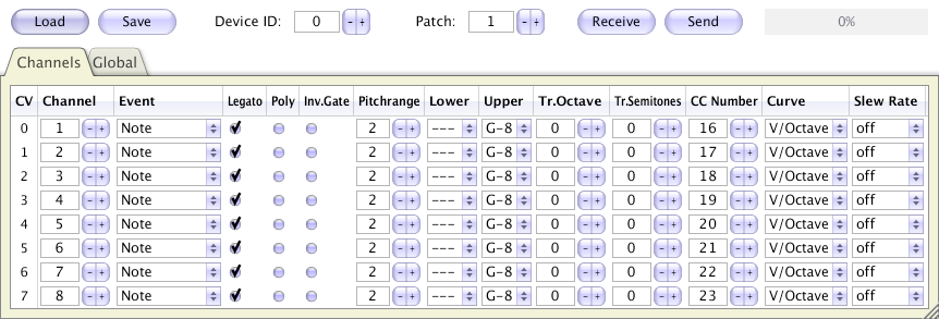
MIDIbox CV Remote Configuration
MIOS Studio 2 contains a tool to configure a MIDIbox CV setup from a PC/Mac:
Future Updates This design is expired! In 2012..2014 MIDIbox CV V2 has been developed which replaced the old version. See this page for more details.
Credits  This is the MIDIbox CV of Francois Buat. He gave me a lot of useful suggestions for improvements, and we tested the firmware together on synths like the Minimoog, Korg MS-20, rsf Kobol Expander, Polykobol II, etc... This is the MIDIbox CV of Francois Buat. He gave me a lot of useful suggestions for improvements, and we tested the firmware together on synths like the Minimoog, Korg MS-20, rsf Kobol Expander, Polykobol II, etc...

Last update: 2025-04-09
Copyright © 1998-2025, Thorsten Klose. All rights reserved.
|