MIDIbox NGUser Manual --- .NGC Configuration FileThis chapter lists all configuration commands and parameters of the .NGC file. If this format is new to you, please read the First Steps chapter first to get a basic understanding.
|
| EVENT Command | Description |
|---|---|
| EVENT_BUTTON | A button can send a MIDI event whenever it's pressed or depressed. If pressed, the maximum value of the specified range will be sent (typically 127), if depressed the minimum value (typically 0). In toggle mode, the on/off state will be updated when it receives the same event. |
| EVENT_LED | A LED can receive a MIDI event. It's turned on if the received value is >= the mid value of the specified range, otherwise it's turned off. |
| EVENT_RGBLED | A WS2812 based RGB LED can receive a MIDI event. By default the received velocity controls the brightness of a pre-configured colour, but it's also possible to control the colour instead. Configuration examples can be found in rgbled_1.ngc |
| EVENT_BUTTON_MATRIX | A button matrix is a hardware option where one or more DIN/DOUT shift registers scan a network of buttons. The corresponding EVENT_BUTTON_MATRIX command sends a value from the specified key or CC number upwards. Toggle mode is not supported! If this is desired, or if individual MIDI events should be sent from the matrix, the events have to be configured with BUTTON_MATRIX button_emu_id_offset=<offset> instead. In this case, the button matrix won't react on EVENT_BUTTON_MATRIX anymore, but on EVENT_BUTTON instead! In order to avoid conflicts with buttons which are directly connected to DIN pins (and which are accessed with BUTTON:1 .. BUTTON:256), it's recommended specify emulated ids outside this range, e.g. button_emu_id_offset=1001. |
| EVENT_LED_MATRIX | A LED matrix is a hardware option where multiple DOUT shift registers scan a network of LEDs. The corresponding EVENT_LED_MATRIX command allows to assign a MIDI event to control individual LEDs of the matrix, or to set a row in the LED matrix to a specified pattern:
In order to avoid conflicts with LEDs which are directly connected to DOUT pins (and which are accessed with LED:1 .. LED:256), it's recommended specify emulated ids outside this range, e.g. led_emu_id_offset=1001. |
| EVENT_ENC | An encoder can send and receive MIDI events. In "absolute mode" it will handle a value internally, in incremental modes it will just send an inc/dec event and expects the handling of the resulting value at the host site. In conjunction with a LED Ring (specified via DOUT_MATRIX) it can display the handled value. It's possible to specify individual led_matrix_pattern for each encoder event. |
| EVENT_AIN | An AIN (core baed analog input) can send and receive MIDI events. Various modes are available, such as "Snap" and "Parallax" to avoid jumping values if a host has notified a value change. |
| EVENT_AINSER | Similar to EVENT_AIN, the AINSER event can send and receive MIDI events. Various modes are available, such as "Snap" and "Parallax" to avoid jumping values if a host has notified a value change. |
| EVENT_MF | A MF (motorfader) event can send and receive MIDI events, and forward them to a MBHP_MF_NG module via MIDI. |
| EVENT_CV | A CV channel can receive a MIDI event and forward the value to the MBHP_AOUT, MBHP_AOUT_LC or MBHP_AOUT_NG module(s). Up to 4 modules are supported, which means that up to 32 channels are available! Note: it isn't possible to mix the module types - so, either 4 MBHP_AOUT, or 4 MBHP_AOUT_LC, or 4 MBHP_AOUT_NG modules can be used! There is a special handling for note events: they are processed through note stacks (each channel has its own) so that MBNG can also be used to play synths from a MIDI keyboard. |
| EVENT_RECEIVER | A receiver is a generic destination which can receive MIDI events and process them according to the specified parameters. It's especially useful as a "forwarding device" to pass received MIDI event values to any other component. A receiver won't send MIDI events. |
| EVENT_SENDER | A sender is a generic source which can send MIDI events when it gets a forwarded event from any other device. This one is especially useful in conjunction with EVENT_RECEIVER for converting or just 1:1 forwarding incoming MIDI event values. A sender won't react on incoming MIDI events. |
Each EVENT_*:
- has an individual ID from id=1 .. id=4095
- can be assigned to a MIDI event such as Note (7bit), CC (7bit), Aftertouch, PitchBend (14bit), NRPN (14bit), SysEx with the type parameter
- can forward the received value to another EVENT_* definition with the fwd parameter
- can listen/send to specified MIDI ports with the ports parameter
- can convert the value to a specified range with the range parameter
- can display a value on the LCD with the lcd_pos and label parameter
- etc... etc...
List of parameters:
| EVENT_* Parameter | Description |
|---|---|
| id=<1..4095> | Specifies the ID of the event which can range from 1..4095. Each EVENT_* element requires a unique ID in the configuration file! The EVENT_<type> is part of the ID, which means that BUTTON, LED, ENC, AINSER can have the same id number. |
| hw_id=<1..4095> | Optionally specifies the hw_id (hardware controller) to which the EVENT definition is assigned. If not specified, the hw_id will match with the id It's possible to trigger multiple events from the same control element (e.g. button or encoder) by assigning them to the same hw_id. The bank and if_* conditions allow to filter the processing. |
| bank=<0..255> | Specifies the bank to which the hw_id is assigned. See also the detailed description in the previous chapter. With bank=0 the controller won't be assigned to any bank, with bank=1..255 it will be assigned, so that the EVENT definition is only active if the selected bank matches with the given number. |
| if_*=<value> if_*=<element>:<hw_id>:<value> |
Specifies a conditional event which either compares the "own" event value, or the event value of another event, with a constant. Following conditional checks are available:
In some usecases it's required to stop the search for events when a condition matched. Just add the _stop_on_match flag in such cases: # the first encoder should send CC#16 over channel 1 if the value is <64 EVENT_ENC id=1 hw_id=1 if_less_stop_on_match=64 type=CC cc=16 chn=1 # and CC#32 over channel 2 if the previous condition didn't stop the processing EVENT_ENC id=101 hw_id=1 type=CC cc=32 chn=2Complete list:
|
| fwd_id=<target:id> fwd_id=<target:id:value> |
Whenever an matching MIDI event has been received, the value can be forwarded to another EVENT element with a specific hw_id:
In conjunction with EVENT_RECEIVER and EVENT_SENDER it's also possible to convert MIDI events, even from "simple" to SysEx and vice versa. Some examples can be found in the First Steps chapter. Multiple events can be chained this way, but the maximum chain length is limited to 4! If a value is passed to an unspecified EVENT id (because you want to avoid unnecessary writing effort), it's assumed that it will have the same parameters like the EVENT which forwards the value. E.g.: EVENT_ENC id=1 fwd_id=LED_MATRIX:1 led_matrix_pattern=1will forward the received value to an EVENT_LED_MATRIX entry with id=1. If this entry hasn't been specified, then it will inherit the parameters of the ENC element. Since the ENC element specified led_matrix_pattern=1, the LED Ring will display the value with pattern #1 Alternatively, it's also possible to forward a constant value. A typical usecase for this option: multiple EVENTs forward to a single, central event to send a specific MIDI command. Example: # whenever CC#16, CC#17 or CC#18 is received, we want to send CC#1 with value 100, 101 or 102 via SENDER:1 EVENT_RECEIVER id=1 fwd_id=SENDER:1:101 type=CC chn= 1 cc= 16 EVENT_RECEIVER id=2 fwd_id=SENDER:1:102 type=CC chn= 1 cc= 17 EVENT_RECEIVER id=3 fwd_id=SENDER:1:103 type=CC chn= 1 cc= 18 EVENT_SENDER id=1 type=CC chn= 1 cc= 1 |
| fwd_to_lcd=<1|0> | Whenever an matching MIDI event has been received, and a label is assigned to the EVENT, and the EVENT is not part of a bank, or the bank is selected, the label will be print on screen. Use this option to display value changes from external on the LCD. |
| type=<event-type> | Specifies the MIDI event type which should be sent and/or received.
|
| chn=<1..16> | Specifies the MIDI channel number (1..16) for NoteOff, NoteOn, PolyPressure, CC, ProgramChange, Aftertouch, PitchBend and NRPN events |
| key=<0..127> key=any |
Specifies the key number (0..127) for type=NoteOff, NoteOn, PolyPressure and Aftertouch events. With key=any the event will take any key number. In combination with the use_key_number flag it's possible to process the received key number instead of the velocity value. |
| kb_transpose=<-128..127> | Only valid for EVENT_KB: specifies the transpose value for the played key from -128..127 |
| kb_velocity_map=map<1..255> | Allows to convert the velocity of a EVENT_KB with a map which consists of 128 values. A usage example can be found in cfg/tests/kb_2.ngc. |
| cc=<0..127> cc=any |
Specifies the CC number (0..127) for type=CC events. With cc=any the event will take any CC number. In combination with the use_cc_number flag it's possible to process the received CC number instead of the CC value. |
| use_key_number=<0|1> use_cc_number=<0|1> |
By default, a Note or CC event will process the velocity or CC value. With use_key_number=1 or use_cc_number=1 the key/CC number will be processed instead. This is especially useful for EVENT_CV to handle the note stack: # these two events listen to any key on channel 1 # the first event uses the "key" as value, sets CV Channel #1 and the CV Gate #1 (at J5A.A0) # the second event uses velocity as value (default) and sets CV Channel #2 EVENT_CV id= 1 type=NoteOn chn= 1 key=any use_key_number=1 fwd_gate_to_dout_pin=1.D7 EVENT_CV id= 2 type=NoteOn chn= 1 key=any use_key_number=0 |
| fwd_gate_to_dout_pin=<1..32>.D<7..0> | Only supported by EVENT_CV: sets the given DOUT pin on Note events. The first number specifies the DOUT shift register (1..32), and the second number the data pin (D7..D0). Example: fwd_gate_to_dout_pin=2.D4 will forward the gate to the D4 pin of the second shift register. |
| nrpn=<0..16383> | Specifies the NRPN number (0..16383) for type=NRPN events |
| nrpn_format=<Unsigned|Signed> | Specifies the NRPN format for a type=NRPN event: Unsigned, Signed or MsbOnly. |
| stream=<...> | Specifies the SysEx stream of a type=SysEx event. The stream is specified as a string with decimal and/or hexadecimal numbers. It can also contain variables which are identified with a Caret (^):stream="0xf0 0x11 0x22 0x33 ^dev 0x00 ^val 0xf7"This example sends and receives a SysEx string starting with "0xf0 0x11 0x22 0x33", then we send/expect the device number, 0x00, the value (which will be passed or send to/from the control element) and 0xf7. Following SysEx variables are available:
|
| meta=<...> | Specifies an operation for type=Meta event:
meta=SetBank meta=DoAnythingElse:42This is just a starting point, much more meta events will be available in future! |
| range=<min-value>:<max-value> range=map<1..255> |
The received/sent value will be scaled to the specified, colon separated, range. For 7bit types such as NoteOn, CC, ... it typically ranges from 0..127 For 14bit types such as PitchBend, NRPN but also SysEx it can also range between -16384..16383 -> try it out! ;-) It's also allowed to specify an ranges such as range=127:0 to invert values. In addition, it's possible to use a MAP for the range (range=map1 .. map255). This powerful feature is described in a separate chapter (search for the MAP command) |
| value=<0..16383> | Specifies the initial value of the event. |
| no_dump=<0 or 1> | Specifies if the current value of the control element should be sent during DumpSnapshot. no_dump=1 is set automatically for EVENT_RECEIVER and EVENT_KB and events which are using type=Meta by default. If such events should be part of the dump, set no_dump=0. For all other events/types no_dump=0 is set by default, set no_dump=1 if they shouldn't send MIDI events on a snapshot dump. |
| offset=<-16384..16383> | Specifies the value offset at which the received value will be displayed in the range of -16384..16383 Only relevant in conjunction with LCD label. Usage example: the received CC value ranges from 0:127, but it should be displayed from -64..63: in this case specify offset=-64 |
| syxdump_pos | type=SysEx events are able to start a ^dump for starting the collection of incoming values. The syxdump_pos parameter selects the value position within the ^dump. Syntax: syxdump_pos=<receiver-id>:<syxdump-pos>. A usage example can be found under cfg/templates/blofeld.ngc. |
| button_mode=<mode> | Following button modes are supported for EVENT_BUTTON:
|
| radio_group=<0..63> | EVENT_BUTTON, EVENT_LED, EVENT_SENDER and EVENT_RECEIVER elements can be assigned to groups, which handle the same value over multiple elements. E.g. let's say, that 8 buttons should send different CC#16 values, and the related LEDs should display the button state. Only one LED should turn on depending on the value which has been sent: EVENT_BUTTON id=1 fwd_id=LED:1 type=CC chn=1 cc=16 button_mode=OnOnly range= 0:0 radio_group=1 EVENT_BUTTON id=2 fwd_id=LED:2 type=CC chn=1 cc=16 button_mode=OnOnly range= 1:1 radio_group=1 EVENT_BUTTON id=3 fwd_id=LED:3 type=CC chn=1 cc=16 button_mode=OnOnly range= 2:2 radio_group=1 EVENT_BUTTON id=4 fwd_id=LED:4 type=CC chn=1 cc=16 button_mode=OnOnly range= 3:3 radio_group=1 EVENT_BUTTON id=5 fwd_id=LED:5 type=CC chn=1 cc=16 button_mode=OnOnly range= 4:4 radio_group=1 EVENT_BUTTON id=6 fwd_id=LED:6 type=CC chn=1 cc=16 button_mode=OnOnly range= 5:5 radio_group=1 EVENT_BUTTON id=7 fwd_id=LED:7 type=CC chn=1 cc=16 button_mode=OnOnly range= 6:6 radio_group=1 EVENT_BUTTON id=8 fwd_id=LED:8 type=CC chn=1 cc=16 button_mode=OnOnly range= 7:7 radio_group=1This also works if only LEDs are used, and it's allowed to use larger ranges: EVENT_LED id= 9 type=CC chn=1 cc= 1 range= 0:9 radio_group=2 EVENT_LED id= 10 type=CC chn=1 cc= 1 range=10:19 radio_group=2 EVENT_LED id= 11 type=CC chn=1 cc= 1 range=20:29 radio_group=2 EVENT_LED id= 12 type=CC chn=1 cc= 1 range=30:39 radio_group=2 EVENT_LED id= 13 type=CC chn=1 cc= 1 range=40:49 radio_group=2 EVENT_LED id= 14 type=CC chn=1 cc= 1 range=50:59 radio_group=2 EVENT_LED id= 15 type=CC chn=1 cc= 1 range=60:69 radio_group=2 EVENT_LED id= 16 type=CC chn=1 cc= 1 range=70:79 radio_group=2 More usage examples:
|
| ain_mode=<mode> | Following ain modes are supported for EVENT_AIN and EVENT_AINSER:
|
| ain_sensor_mode=<mode> | Following sensor modes are supported for EVENT_AIN and EVENT_AINSER:
|
| ain_filter_delay_ms=<delay> | Experimental option for sensors. See also ain_fsr.ngc |
| enc_mode=<mode> | Following encoder modes are supported for EVENT_ENC:
|
| enc_speed_mode=<mode:par> | The encoder speed mode allows to modify the speed response of an EVENT_ENC:
|
| emu_enc_mode=<mode> | Encoder events can also be emulated from external via MIDI by using an EVENT_RECEIVER, and setting the emu_enc_mode and emu_enc_hw_id. See also following configuration example: emu_enc.ngc. Following encoder modes can be emulated by a EVENT_RECEIVER:
|
| emu_enc_hw_id=<1..128> | Specifies the encoder hw_id which should be incremented by a EVENT_RECEIVER. See also emu_enc_mode. |
| led_matrix_pattern=<pattern-number> | LED patterns can be specified if an event should forward its value to a LED_MATRIX element:
|
| colour=<0..2> | Specifies the color layer of the LED_MATRIX:
|
| dimmed=<0 or 1> | LEDs can now be dimmed with 16 brightness levels over the value range. This feature has to be enabled with dimmed=1 in the EVENT_* definition. Configuration example: cfg/test/dimled.ngc. LEDs in a matrix configuration can be dimmed as well. The dim range is the same (0..15), but the effective dim level is limited by the number of scanned rows:
|
| rgb=<red>:<green><blue> | In distance to the dimmed option, the rgb parameter allows to set preconfigured brightness levels for the three LED layers of a LED matrix. All three values range from 0..15. Configuration Examples:
Note2: rgb will also work for WS2812 based RGBLEDs, but due to the higher resolution the hsv parameter described below is prefered. |
| hsv=<hue>:<saturation><brightness> | This command will only work for WS2812 based RGBLEDs! Sets the hue/saturation/value colour code of a WS2812 based RGBLED. H ranges from 0..359 (grad); saturation and value (brightness) range from 0..100 (percentage) Configuration Example:
|
| inverted=<0|1> | Only relevant for EVENT_BUTTON and EVENT_LED: with inverted=1 the DIN input resp. DOUT output will be inverted. |
| cv_inverted=<0|1> | Only relevant for EVENT_CV: with cv_inverted=1 the CV output will be inverted. |
| cv_hz_v=<0|1> | Only relevant for EVENT_CV:
|
| cv_gate_inverted=<0|1> | Only relevant for EVENT_CV: with cv_gate_inverted=1 the CV gate output (specified with fwd_gate_to_dout_pin will be inverted. |
| ports=<port-selections> | Expects a 16bit binary value (0|1) to select the MIDI ports over which the event should send and receive:
ports=10001000000010000000will enable USB1, MIDI1 (IN1 and OUT1) and OSC1, and following binary: ports=00001100000000000000will only enable MIDI1 and MIDI2 ports=00000000000000001000will enable SPI1 |
| lcd_pos=<lcd>:<X>:<Y> | Each event can output a label whenever a value has been received via MIDI, or the control element has been moved (e.g. button has been pushed, encoder/motorfader/pot has been moved). lcd specifies the LCD number which should be used to output the label, X the column and Y the line. E.g.: lcd_pos=1:1:1will output the label on the first LCD, first character in the first line. And: lcd_pos=1:1:2will output the label on the first LCD, first character in the second line. |
| label=<string> | Specifies the label (string) which should be output at the specified lcd_pos. The string can contain printf-linke control characters to output formatted values or strings, and it can contain references to globally defined labels of the .NGL file.
lcd_pos=1:1:1 label="ENC #%3i %3d%B"will output at the first LCD, first column, first line a string with 20 characters. It starts with "ENC #", followed by the ID of the EVENT_ENC (3 digits), some spaces, the EVENT value (3 digits right-aligned) and a vertical bar. lcd_pos=1:1:1 label="FIL1 Type ^fil_type"will output "FIL1 Type " and then a conditional label called ^fil_type which has been specified in the .NGL file. GLCDs can output different fonts which are selected with the ampersant (&) character:
lcd_pos=1:1:1 label="Enc%3i&k@(1:1:2)%B&n@(1:18:1)%3d"No, this is not an encrypted message, because the processing rules are well documented! ;-) - it will output "ENC" + the ID number. Then it will select the "knob" icon, jump to position X=1 Y=2 and output the knob icon based on the EVENT value. Thereafter it will select the normal font, jump to position X=18 Y=1 and output the MIDI value in decimal format. |
 MAP<n>
This command creates a map of values which can be used by EVENTs for alternative value ranges without continuous values.
E.g., consider that an encoder should only send following values:
MAP1 1 2 4 8 16 32 64
Then select this map with:
EVENT_ENC    id=  1  fwd_id=LED_MATRIX:1  fwd_to_lcd=1 \
                     type=CC chn= 1 cc= 16  range=map1  lcd_pos=1:1:1  label="^std_enc"
Up to 255 maps can be defined (MAP1 .. MAP255). Four different types are available:
| MAP | Description |
|---|---|
| MAP<n> or MAP<n>/BYTE | Up to 256 values can be specified, the value range is 0..255 (8bit) Example: MAP1/BYTE 1 2 4 8 32 64 |
| MAP<n>/HWORD | Up to 128 values can be specified, the value range is -16384..16383 (16bit) Example: MAP1/HWORD 1 2 4 8 32 64 128 256 512 1024 4096 8192 |
| MAP<n>/BYTEI | Applies linear interpolation between data points. This allows to quickly define curves without the need to enter the values for the complete range. E.g. with MAP/BYTE it is required to enter 256 values to create a curve for a CC controller, with MAP/BYTEI it's mostly sufficient to define the same with 3..4 data points. MBNG will interpolate the values between these points. Up to 128 datapoints can be specified, the value range is 0..255 (8bit). Example: # using an interpolation map to define the velocity curve MAP1/BYTEI 0:0 64:30 96:80 127:127 |
| MAP<n>/HWORDI | Applies linear interpolation between data points. Up to 64 datapoints can be specified, the value range is -16384..16383 (16bit). Example: # pot is working at 12bit resolution (0..4095) # 0..2048 should send CC value 127..0 downwards, # and 2049..4095 (the second half) should send 0..127 upwards. MAP1/HWORDI 0:127 2048:0 4095:127 |
The various control elements use maps the following way:
- EVENT_ENC: send a mapped value with enc_mode=Absolute - configuration example
- EVENT_AIN and EVENT_AINSER: send a mapped value - configuration example
- EVENT_MF: send a mapped value - configuration example
- EVENT_BUTTON: with button_mode=Toggle a single button can cycle between the map values - configuration example
- EVENT_SENDER and EVENT_RECEIVER: the sent/received value will be mapped - configuration example
SYSEX_VAR
This command specifies the default values of various SysEx variables, which are available for EVENT_* stream="...":
| SYSEX_VAR Parameter | Description |
|---|---|
| dev=<0..127> | the Device ID (^dev) |
| pat=<0..127> | the Patch number (^pat) |
| bnk=<0..127> | the Bank number (^bnk) |
| ins=<0..127> | the Instrument number (^ins) |
| chn=<0..127> | the Channel number (^chn) |
The variables could also be used for other purposes of course, they are only placeholders for typical usecases.
ENC
The ENC command configures rotary encoders which are connected to a MBHP_DIN module:
| ENC Parameter | Description |
|---|---|
| n=<1..128> | Specifies the encoder number which should be configured; it can range from 1..128 |
| sr=<1..16> | Sets the DIN shift register to which the encoder is connected. 1 stands for the first DIN in the chain, 2 for the second, etc... |
| pins=<pin-a>:<pin-b> | Sets the pair of digital input pins of the DIN shift register to which the encoder is connected. The allowed pinning is restricted to following combinations:
|
| type=<name> | Sets the encoder type: non_detented, detented1, detented2 or detented3. A documentation about these types can be found in this Wiki article. |
DIN_MATRIX
The DIN_MATRIX command configures button matrices which are connected between DIN/DOUT shift registers. Please note that all assigned shift registers can't be used for common button or LED functions anymore:
| DIN_MATRIX Parameter | Description |
|---|---|
| n=<1..8> | Specifies the matrix number which should be configured; it can range from 1..8 |
| rows=<4|8|16> | Sets the number of rows which should be scanned:
|
| inverted=<1|0> inverted_sel=<1|0> |
DOUT selection lines will be inverted with inverted=1 or inverted_sel=1. This is required if the diodes of the button matrix have been connected in the opposite order:
|
| inverted_row=<1|0> | DIN row patterns can be inverted with inverted_row=1 |
| sr_dout_sel1=<0..16> | Sets the first DOUT shift register which should output the row selection signals. |
| sr_dout_sel2=<0..16> | Sets the second DOUT shift register which should output the row selection signals in a row=16 setup. Set this parameter to 0 if a second DOUT is not required. |
| sr_din1=<0..16> | Sets the first DIN shift register of the button matrix. |
| sr_din2=<0..16> | Sets the (optional) second DIN shift register of the button matrix. |
| mirrored_row=<1|0> | The pins of a DIN row can be mirrored. This happens only for the shift register value itself. Means: if two DIN shift registers are assigned to the row, they won't be swapped. If this is desired, just change the sr_din1/sr_din2 assignments. |
| button_emu_id_offset=<1..4095> | With a value >0, the button matrix will trigger EVENT_BUTTON events instead of EVENT_BUTTON_MATRIX, starting with the specified ID. A matrix of 8x8 buttons can emulate 64 buttons with individual event assignments this way. In order to avoid conflicts with buttons which are directly connected to DIN pins (and which are accessed with BUTTON:1 .. BUTTON:256), it's recommended specify emulated ids outside this range, e.g. button_emu_id_offset=1001. |
DOUT_MATRIX
The DOUT_MATRIX command configures LED matrices which are connected between multiple DOUT shift registers.
Usecases:
- Already with 2 DOUT shift registers it's possible to control 64 LEDs. One DOUT is used to select the column, the second DOUT to set the row pattern. By using the led_emu_id_offset parameter they behave like common EVENT_LED elements and can be controlled individually. This saves some hardware! (only 2 DOUT shift registers instead of 8 to drive 64 LEDs).
Other useful hardware configurations: with 1 DOUT assigned to the column, and two assigned to the row, up to 128 LEDs can be controlled from 3 DOUT shift registers. With two DOUTs assigned to the column, and two assigned to the row, up to 256 LEDs can be controlled from 4 DOUT shift registers. - Actually each matrix provides three separate "row layers", called r, g, b (red, green, blue). You get the message: this allows you to control multicolour LEDs!
- LED Rings and Meters - see also the LED_MATRIX_PATTERN configuration below. The led_matrix_pattern can be passed from a control element (e.g. EVENT_ENC) to the LED matrix in order to output a pattern based on the event value.
- LED Digits (7-segment displays) are controlled from a DOUT_MATRIX as well. Here are some interconnection diagrams with the appr. .NGC configuration examples:
Available configuration parameters:
| DOUT_MATRIX Parameter | Description |
|---|---|
| n=<1..8> | Specifies the matrix number which should be configured; it can range from 1..8 |
| rows=<4|8|16> | Sets the number of rows which should be scanned:
|
| inverted=<1|0> | DOUT selection lines will be inverted with inverted=1. This is required if the LEDs of the matrix have been connected in the opposite order:
|
| inverted_row=<1|0> | DOUT row patterns can be inverted with inverted_row=1 |
| sr_dout_sel1=<0..16> | Sets the first DOUT shift register which should output the row selection signals. |
| sr_dout_sel2=<0..16> | Sets the second DOUT shift register which should output the row selection signals in a row=16 setup. Set this parameter to 0 if a second DOUT is not required. |
| sr_dout_r1=<0..16> | Sets the first DOUT shift register of the LED matrix row. |
| sr_dout_r2=<0..16> | Sets the (optional) second DOUT shift register of the LED matrix row. |
| sr_dout_g1=<0..16> sr_dout_g2=<0..16> |
These parameters allow to drive duo-colour or RGB LEDs by using a second set of DOUTs connected to the green LEDs. |
| sr_dout_b1=<0..16> sr_dout_b2=<0..16> |
These parameters allow to drive RGB LEDs by using a third set of DOUTs connected to the blue LEDs. |
| mirrored_row=<1|0> | The pins of the DOUT rows can be mirrored. This happens only for the shift register value itself. Means: if two DOUT shift registers are assigned to the row, they won't be swapped. If this is desired, just change the sr_dout_r1/sr_dout_r2 assignments. |
| led_emu_id_offset=<1..4095> | With a value >0, the LED matrix will listen on EVENT_LED events instead of EVENT_LED_MATRIX, starting with the specified ID. A matrix of 8x8 LED can emulate 64 LEDs with individual event assignments this way. In order to avoid conflicts with LEDs which are directly connected to DOUT pins (and which are accessed with LED:1 .. LED:256), it's recommended specify emulated ids outside this range, e.g. led_emu_id_offset=1001. |
| lc_meter_port=<USB1..USB4|IN1..IN4> | Special option for the Logic/Mackie Control emulation. It allows to transfer incoming Poly Preasure events (which are used by the protocol to trigger the meters) to LED bars. An usage example can be found in following template (search for "meter"): logictrl.ngc |
Please note that all assigned shift registers can't be used for other purposes anymore! E.g. if only 4 rows are scanned, and accordingly only 4 pins are used to select the columns, the remaining 4 pins of the shift register can't be used to control 4 LEDs directly!
LED_MATRIX_PATTERN
The LED_MATRIX_PATTERN command is used in conjunction with LED Rings to configure the output based on an incoming value for EVENT_MATRIX_DOUT elements with the led_matrix_pattern parameter. Optionally the pattern can also be selected by a EVENT_ENC element if no EVENT_MATRIX_DOUT event has been defined.
Each pattern-set consists of 17 entries. 16 entries are scaled over the specified min/max range of incoming value. The 17th entry is called 'M' and is used when the middle of the value range has been reached.
Examples for a typical patterns for a LED Ring with 11 LEDs, and a 12th "center" LED (see also this schematic):
# LED_MATRIX_PATTERNs
LED_MATRIX_PATTERN n= 1  pos= 0  pattern=1000000000000000
LED_MATRIX_PATTERN n= 1  pos= 1  pattern=1100000000000000
LED_MATRIX_PATTERN n= 1  pos= 2  pattern=1100000000000000
LED_MATRIX_PATTERN n= 1  pos= 3  pattern=1110000000000000
LED_MATRIX_PATTERN n= 1  pos= 4  pattern=1110000000000000
LED_MATRIX_PATTERN n= 1  pos= 5  pattern=1111000000000000
LED_MATRIX_PATTERN n= 1  pos= 6  pattern=1111000000000000
LED_MATRIX_PATTERN n= 1  pos= 7  pattern=1111100000000000
LED_MATRIX_PATTERN n= 1  pos= M  pattern=1111110000010000
LED_MATRIX_PATTERN n= 1  pos= 8  pattern=1111111000000000
LED_MATRIX_PATTERN n= 1  pos= 9  pattern=1111111100000000
LED_MATRIX_PATTERN n= 1  pos=10  pattern=1111111100000000
LED_MATRIX_PATTERN n= 1  pos=11  pattern=1111111110000000
LED_MATRIX_PATTERN n= 1  pos=12  pattern=1111111110000000
LED_MATRIX_PATTERN n= 1  pos=13  pattern=1111111111000000
LED_MATRIX_PATTERN n= 1  pos=14  pattern=1111111111000000
LED_MATRIX_PATTERN n= 1  pos=15  pattern=1111111111100000

LED_MATRIX_PATTERN n= 2  pos= 0  pattern=1111110000000000
LED_MATRIX_PATTERN n= 2  pos= 1  pattern=0111110000000000
LED_MATRIX_PATTERN n= 2  pos= 2  pattern=0111110000000000
LED_MATRIX_PATTERN n= 2  pos= 3  pattern=0011110000000000
LED_MATRIX_PATTERN n= 2  pos= 4  pattern=0001110000000000
LED_MATRIX_PATTERN n= 2  pos= 5  pattern=0001110000000000
LED_MATRIX_PATTERN n= 2  pos= 6  pattern=0000110000000000
LED_MATRIX_PATTERN n= 2  pos= 7  pattern=0000010000000000
LED_MATRIX_PATTERN n= 2  pos= M  pattern=0000111000010000
LED_MATRIX_PATTERN n= 2  pos= 8  pattern=0000010000000000
LED_MATRIX_PATTERN n= 2  pos= 9  pattern=0000011000000000
LED_MATRIX_PATTERN n= 2  pos=10  pattern=0000011000000000
LED_MATRIX_PATTERN n= 2  pos=11  pattern=0000011100000000
LED_MATRIX_PATTERN n= 2  pos=12  pattern=0000011110000000
LED_MATRIX_PATTERN n= 2  pos=13  pattern=0000011110000000
LED_MATRIX_PATTERN n= 2  pos=14  pattern=0000011111000000
LED_MATRIX_PATTERN n= 2  pos=15  pattern=0000011111100000

LED_MATRIX_PATTERN n= 3  pos= 0  pattern=1000000000000000
LED_MATRIX_PATTERN n= 3  pos= 1  pattern=0100000000000000
LED_MATRIX_PATTERN n= 3  pos= 2  pattern=0100000000000000
LED_MATRIX_PATTERN n= 3  pos= 3  pattern=0010000000000000
LED_MATRIX_PATTERN n= 3  pos= 4  pattern=0010000000000000
LED_MATRIX_PATTERN n= 3  pos= 5  pattern=0001000000000000
LED_MATRIX_PATTERN n= 3  pos= 6  pattern=0000100000000000
LED_MATRIX_PATTERN n= 3  pos= 7  pattern=0000010000000000
LED_MATRIX_PATTERN n= 3  pos= M  pattern=0000111000010000
LED_MATRIX_PATTERN n= 3  pos= 8  pattern=0000010000000000
LED_MATRIX_PATTERN n= 3  pos= 9  pattern=0000001000000000
LED_MATRIX_PATTERN n= 3  pos=10  pattern=0000000100000000
LED_MATRIX_PATTERN n= 3  pos=11  pattern=0000000100000000
LED_MATRIX_PATTERN n= 3  pos=12  pattern=0000000010000000
LED_MATRIX_PATTERN n= 3  pos=13  pattern=0000000001000000
LED_MATRIX_PATTERN n= 3  pos=14  pattern=0000000001000000
LED_MATRIX_PATTERN n= 3  pos=15  pattern=0000000000100000
| LED_MATRIX_PATTERN Parameter | Description |
|---|---|
| n=<1..4> | Specifies the pattern-set number; it can range from 1..4 |
| pos=<0..15|M> | Specifies the position for the following pattern (0..15, or M for middle position) |
| pattern=<16-bit-binary> | Sets the pattern for the given position. It consists of 16 binary digits (0 or 1 for LED off/on) |
SRIO
| SRIO Command | Description |
|---|---|
| num_sr=<1..32> | By default 32 DIN and DOUT shift registers are scanned, which result into an update rate of ca. 420 uS on a STM32F4 based core. With (for example) SRIO sr_num=8 only up to 8 DIN and 8 DOUT SRs will be scanned anymore, but the update rate is reduced to ca. 110..120 uS (a little bit more than a quarter due to SR handling overhead). |
| debounce_cycles=<0..65535> | This command allows to enable a debouncing mechanism for digital inputs (buttons). The number specifies the dead time in SRIO cycles at which button events will be rejected. The time of a SRIO cycle depends on the num_sr configuration, typically it's around 420 uS for 32 SRs, which means that with debounce_cycles=20 the debouncing dead time is 8.4 mS. |
DIO
The DIO command has been added for MBHP_CORE_STM32F4 users who want to start with a very simple MIDIbox NG setup and only need a small number of digital inputs and outputs (e.g. for buttons, encoders and/or LEDs), and don't want to connect serial shift registers (MBHP_DINX4, MBHP_DOUTX4, MBHP_DIO_MATRIX). In this case, J10A and J10B can be used for up to 16 digital pins. Each J10 port can overrule a DIN or DOUT shift register.
| DIO Parameter | Description |
|---|---|
| port=<port-name> | Specifies the IO port which should be configured:
|
| emu_din_sr=<1..32> | The selected port will overrule a DIN shift register position, so that 8 inputs are available. Note that internal pull-up devices will be enabled, which means that buttons could be connected directly between J10 pins and ground. Note that you can't specify emu_dout_sr in addition for the same port. The entire port is either configured for inputs our outputs! |
| emu_dout_sr=<1..32> | The selected port will overrule a DOUT shift register position, so that 8 outputs at 3.3V are available. Note that you can't specify emu_din_sr in addition for the same port. The entire port is either configured for inputs our outputs! |
- diocfg_1.ngc: use J10A and J10B for up to 16 buttons
- diocfg_2.ngc: use J10A for 8 buttons, and J10B for 8 LEDs
KEYBOARD
The KEYBOARD command configures (hardware) keyboards. The same driver like for MIDIbox KB is used, but the scan frequency is slower (10 times!). Each row is scanned in 320 uS (instead of 32 uS). This has to be considered in the velocity delay configuration: delay_slowest should be 100 (instead of 1000), and delay_fastest should be 5 (instead of 50)
Here a typical keyboard configuration for a Fatar DF type with 61 keys:
KEYBOARD n=1   rows=8  dout_sr1=1  dout_sr2=2  din_sr1=1  din_sr2=2 \
               din_inverted=0  break_inverted=0  din_key_offset=32 \
               make_debounced=0 \
               scan_velocity=1  scan_optimized=0  note_offset=28 \
               delay_fastest=5  delay_fastest_black_keys=0  delay_slowest=100

EVENT_KB id=1  type=NoteOn chn=1 key=any use_key_number=1 range=0:127  lcd_pos=1:1:1 label="Note %n"
Configuration examples:
- kb_1.ngc: simple configuration
- kb_2.ngc: usage of a velocity map
- kb_3.ngc: splitting keyboard into two zones
- kb_4.ngc: forwarding to CV outputs
- kb_5.ngc: using the KbBreakIsMake option
- kb_6.ngc/kb_6.ngr: selectable transpose and velocity map
Please note, that the configuration commands are identical "set kb..." as documented at the MIDIbox KB page. This means, that the keyboard parameters can also be changed during runtime to determine the best matching values, before they are written into the .NGC file.
Optionally the delay_slowest values can be calibrated for each individual key of the keyboard. The values are stored in the .NGK file, and can be edited with the MIOS Filebrowser.
AIN
The AIN command allows to enable/disable core based analog inputs with the enable_mask parameter. It consists of 6 binary digits which stand for J5A.A0..J5B.A5
Example:
# AIN hardware
AIN enable_mask=110000
will enable the J5A.A0 and J5A.A1 inputs.
In addition, it's possible to specify the physical min/max limits for each individual input pin with this command, example:
AIN pinrange=1:18:4065
AIN pinrange=2:18:4065
Syntax: pinrange=<pin>:<min>:<max>[<:spread_center>]
Purpose: under certain circumstances, a connected potentiometer doesn't output 0V on the min position, and/or 3.3V on the max position due to physical limitations. The pinrange parameter allows to overcome this by scaling the received conversion values to the full 0..4095 range.
In order to find out the value range of a pot, please activate the debug mode by entering set debug on in the MIOS Terminal. This mode will output the original conversion values whenever the pot is moved. The minimum/maximum displayed values are the ones which have to be specified with the pinrange parameter.
If a Pitchwheel (a pot which snaps to the center position) is connected, you may notice that the middle value won't always be reached due to mechanical reasons.
In order to solve this issue, the :spread_center option can be used:
AIN pinrange=1:18:4065:spread_center
It spreads the deadband around the center position by +/- 40 (in 12bit resolution) to ensure a reliable middle value when the Pitchwheel snaps back.
Please note: unconnected analog inputs which haven't been disabled will generate random MIDI event values! It's strongly recommended to disable unused pins in the enable_mask, or to connect these pins to ground!
AINSER
The AINSER command configures the MBHP_AINSER64 resp. MBHP_AINSER8 module:
| AINSER Parameter | Description |
|---|---|
| n=<1..2> | Specifies the AINSER module which should be configured (1 or 2) |
| enabled=<0|1> | Enables the module with 1, disables the module with 0 so that it doesn't generate EVENT_AINSER events. |
| muxed=<0|1> | Enables the multiplexers of a AINSER64 module with muxed=1 (default). Use muxed=0 for the AINSER8 module. Please note that regardless of the muxed setting, the pin number (and accordingly hw_id) of the second module always starts at offset 65. |
| cs=<0|1> | Specifies the "chip select" line which is jumpered with J4 of the module. Each module has to be configured for a dedicated chip select line! cs=0 selects CS1, cs=1 selects CS2 (sorry for the confusion...) |
| resolution=<4..12bit> | Specifies the resolution at which the analog inputs should be scanned. By default the pins are scanned at 7bit resolution. Up to 12bit is supported, but in this case there won't be any (deadband based) jitter rejection. So, the recommended values are:
If you should still notice jittering values with this resolution, try lower options such as 10bit or 9bit first - maybe this already satisies your needs before you've to spend a lot of effort into hardware improvements. Please note that the resolution setting is independent from the resolution sent by a MIDI event. This one will be scaled automatically to the target resolution depending on the specified range! |
| num_pins=<1..64> | Specifies the number of scanned analog input pins. By default all 64 pins of the MBHP_AINSER module will be scanned. It makes sense to specify a lower number of the upper analog inputs are not connected (even not to ground) to avoid the generation of random values due to the floating inputs. |
| pinrange=<pin>:<min>:<max>[<:spread_center>] | Specifies the physical min/max limits for each individual input pin with this command, example:
AINSER pinrange=1:18:4065
AINSER pinrange=2:18:4065
Purpose: under certain circumstances, a connected potentiometer doesn't output 0V on the min position, and/or 3.3V on the max position due to physical limitations. The pinrange parameter allows to overcome this by scaling the received conversion values to the full 0..4095 range. In order to find out the value range of a pot, please activate the debug mode by entering set debug on in the MIOS Terminal. This mode will output the original conversion values whenever the pot is moved. The minimum/maximum displayed values are the ones which have to be specified with the pinrange parameter. If a Pitchwheel (a pot which snaps to the center position) is connected, you may notice that the middle value won't always be reached due to mechanical reasons. In order to solve this issue, the :spread_center option can be used: AINSER pinrange=1:18:4065:spread_centerIt spreads the deadband around the center position by +/- 40 (in 12bit resolution) to ensure a reliable middle value when the Pitchwheel snaps back. |
MF
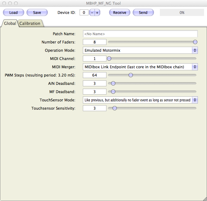
The MF command configures the MBHP_MF_NG module. The module has to be configured for "Motormix" emulation, because this protocol allows to send and receive fader movements over dedicated MIDI channels with 14bit resolution. It's allowed to connect multiple modules in a MIDI chain, in such a case the MIDI merger has to be configured as "MIDIbox Link Endpoint" for the last module, and as "MIDIbox Link Forwarding Point" for the remaining modules in the MBHP_MF_NG configuration tool which is part of MIOS Studio:
List of parameters:
| MF Parameter | Description |
|---|---|
| n=<1..4> | Specifies the MF module which should be configured (1..4) |
| enabled=<0|1> | Enables the module with 1, disables the module with 0 so that it doesn't generate EVENT_MF events. |
| midi_in_port=<IN1..IN4> | Sets the MIDI IN port to which the module is connected (IN1..IN4) Please ensure that this port is not used by the MIDI_ROUTER. |
| midi_out_port=<OUT1..OUT4> | Sets the MIDI OUT port to which the module is connected (OUT1..OUT4) Please ensure that this port is not used by the MIDI_ROUTER. |
| config_port=<USB1..USB4> | Sets the USB port over which the MBHP_MF_NG module should be configured (with the MIOS Studio based tool described above). It's recommended not to use USB1 for SysEx accesses (including firmware updates), since MIOS32 listens to the same port for firmware updates if it's assigned to the same SysEx Device ID. Any other USB port (USB2..USB4) will work without such potential collisions. |
| chn=<1..16> | Sets the MIDI channel over which the MBHP_MF_NG module will send and receive fader movements |
| ts_first_button_id=<0..4095> | With a value >0, touch sensor events generated by the MBHP_MF_NG module will trigger EVENT_BUTTON elements with the specified ID upwards. This allows to convert these events into any over MIDI output (and/or to display them on the LCD) |
AOUT
This command configures the AOUT module:
List of parameters:
| AOUT Parameter | Description |
|---|---|
| type=<aout-type> | Specifies the AOUT module which is connected to port J19 of the MBHP_CORE_LPC17 module:
|
| cs=<0|1> | Specifies the "chip select" line which to which the AOUT module is connected:
|
| num_channels=<1..32> | Specifies the number of channels which should be controlled via EVENT_CV events. The channel number corresponds with the EVENT id |
Configuration example:
# initialize the AOUT module
AOUT  type=AOUT_NG  cs=0  num_channels=8
Complete examples:
SCS
SCS stands for "Standard Control Surface" which is explained in the SCS chapter.
The SCS command allows to define the emulated button and encoder IDs which are used when the SCS is in the main page.
List of parameters:
| AOUT Parameter | Description |
|---|---|
| soft1_button_emu_id=<0..4095> soft2_button_emu_id=<0..4095> soft3_button_emu_id=<0..4095> soft4_button_emu_id=<0..4095> soft5_button_emu_id=<0..4095> soft6_button_emu_id=<0..4095> soft7_button_emu_id=<0..4095> soft8_button_emu_id=<0..4095> shift_button_emu_id=<0..4095> |
A SCS button will emulate the specified BUTTON ID if the SCS is in the main page. If the id is set to 0, the button function won't have any effect! |
| enc_emu_id=<0..4095> | A SCS encoder will emulate the specified ENC ID if the SCS is in the main page. If the id is set to 0, the encoder function won't have any effect! |
| lcd_pos=<lcd>:<X>:<Y> | Specifies the LCD position at which the SCS menu page will be print when the MENU button is pressed.
The SCS allocates two lines on the LCD. The width of the SCS page depends on the number of items: each item consumes 5 characters. With the default value num_items=4 the page spans over a 2x20 screen. |
| num_items=<1..8> | Specifies the number of items which are handled in a SCS page. This also defines the screen size which is alloctated by the SCS when the menu system is active (MENU button pressed). Meaningful values:
|
Configuration example:
# the SCS should emulate button/enc functions in main page
SCS soft1_button_emu_id=2000 \
    soft2_button_emu_id=2001 \
    soft3_button_emu_id=2002 \
    soft4_button_emu_id=2003 \
    shift_button_emu_id=2004 \
    enc_emu_id=2000


# Controlled from SCS buttons at J10 in main page
EVENT_BUTTON id=2000  type=Meta   meta=SetBank   button_mode=OnOnly range=1:1  lcd_pos=1:17:1 label="Bnk%q"
EVENT_BUTTON id=2001  type=Meta   meta=SetBank   button_mode=OnOnly range=2:2  lcd_pos=1:17:1 label="Bnk%q"
EVENT_BUTTON id=2002  type=Meta   meta=SetBank   button_mode=OnOnly range=3:3  lcd_pos=1:17:1 label="Bnk%q"
EVENT_BUTTON id=2003  type=Meta   meta=SetBank   button_mode=OnOnly range=4:4  lcd_pos=1:17:1 label="Bnk%q"
EVENT_BUTTON id=2004  type=Meta   meta=EncFast:4 button_mode=OnOff  range=0:2

# the SCS encoder at J10 just increments/decrements the bank
# redundant function - could be changed in future
EVENT_ENC    id=2000  type=Meta   meta=SetBank   range=1:4
ROUTER
The integrated MIDI router consists of 16 "nodes". Each node can be connected to an individual source and destination port. A node is activated by selecting a source MIDI channel != "--", e.g. 1..16 or All (for all channels). The node will forward a MIDI event to the destination port. Either to the original channel ("All"), or to a changed channel (1..16).
List of parameters:
| ROUTER Parameter | Description |
|---|---|
| n=<1..16> | Specifies the ROUTER node which should be configured (1..16) |
| src_port=<port> | Specifies the source port from which MIDI events should be forwarded:
|
| src_chn=<0..17> | Allows to select a dedicated channel which should be forwarded:
|
| dst_port=<port> | Specifies the destination port to which MIDI events should be forwarded:
|
| dst_chn=<0..17> | Allows to convert the incoming MIDI channel:
|
Please note: the MIDI router can also be configured during runtime in the MIOS Terminal with the "set router" command. "router" will output an oversight over the complete configuration.
ETH
The ETH command allows to configure the ethernet interface of the MBHP_CORE_LPC17 module:
| ETH Command | Description |
|---|---|
| dhcp=<0|1> | if enabled (default), the Host IP, Network Mask and Gateway address will be requested from a DHCP Daemon (e.g. your wireless router) automatically whenever the ethernet cable is connected. The configuration could take some seconds depending on the responsiveness of your router. |
| local_ip=<ip> | Sets the IP address of your MIDIbox NG directly if dhcp=0 |
| netmask=<mask> | Sets the netmask of your MIDIbox NG directly if dhcp=0 |
| gateway=<ip> | Sets the IP address of the gateway (typically your router) directly if dhcp=0 |
OSC
The OSC command configures the OSC ports. More details about the MIOS32 based OSC implementation can be found at this page.
List of parameters:
Each OSC port has an individual remote IP, a remote port (to which OSC packets will be sent) and a local port (from which OSC packets will be received):
| OSC Command | Description |
|---|---|
| n=<1..4> | Specifies the OSC port which should be configured (1..4) |
| remote_ip=<ip> | Sets the remote IP assigned to the OSC port (e.g. the IP of your iPad) |
| remote_port=<ip> | Sets the remote port to which OSC packets will be sent |
| local_port=<ip> | Sets the local port from which OSC packets will be received |
| transfer_mode=<format> | Following transfer formats are currently supported:
|
MidiClkOutPorts and MidiClkInPorts
MidiClkOutPorts <ports>: sets the MIDI clock output ports
MidiClkInPorts <ports>: sets the MIDI clock input ports
GlobalChannel
GlobalChannel <0..16>: if set to a value >0, all MIDI events generated with EVENT_* commands will be forced to the given MIDI channel. not implemented yet!
AllNotesOffChannel
AllNotesOffChannel <0..16>: if set to a value >0, the CC#123 event will turn off all LEDs when received over the specified channel
ConvertNoteOffToOn0
ConvertNoteOffToOn0 <0|1>: if set to 1, incoming NoteOff events will be converted to NoteOn with velocity 0. This option is enabled by default to simplify the configuration of receivers (e.g. LEDs) which should be turned off on any NoteOff event, including NoteOn with velocity 0 which has the same purpose (according to the MIDI spec).
If set to 0, this simplification doesn't take place, so that NoteOn and NoteOff events can be handled separately.
RESET_HW
The RESET_HW command can be set at the top of a .NGC file to reset the complete configuration. This is especially useful if your file only specifies a small number of settings, so that the remaining hardware is in a "known state".
This command shouldn't be specified in files which contain partial setups, e.g. an alternative EVENT_* configuration for your hardware, or different ROUTER and OSC settings which you could load during runtime without overwriting the actual controller setup.
LCD
The LCD command prints an immediate message on screen while it's executed.
It can be used to initialize the LCDs with static text, or just to display the purpose of your file before an EVENT_* based label overwrites the message.
All string control formats and directives are supported (see description of EVENT_* label parameter), which especially means that it's possible to clear the screen, and to jump to different cursor positions at different displays.
Example:
LCD "%C@(1:1:1)Hello World!"
![]()
Last update: 2026-03-13
Copyright © 1998-2026, Thorsten Klose. All rights reserved.