Back to main page...
MIDIbox NG
User Manual --- Hardware Options
MIDIbox NG is flexible enough to handle almost all modules of the MIDIbox Hardware Platform (exeptions are MBHP_SID and MBHP_OPL3 which require a synthesizer engine... ;-)
This page is under construction! It's currently only a rough draft which collects the supported modules, and will contain more detailed informations in future!
 MBHP_CORE_LPC17 or MBHP_CORE_STM32F4 MBHP_CORE_LPC17 or MBHP_CORE_STM32F4

The MBHP_CORE_LPC17 module is the brain of the MIDI controller. Today (2013) it's a state-of-the-art solution for such a purpose, especially because of the high performance, the 4 MIDI IN and OUT ports, integrated USB-MIDI and Ethernet interface.

The MBHP_CORE_STM32F4 module is more powerful (e.g. faster and more RAM) and less expensive - only drawback is the missing integrated ethernet interface, but a MBHP_ETH module could be used instead if OSC messages should be sent and received.
Note: MBHP_CORE_STM32F4 allows to execute NGR scripts directly from RAM, therefore it's the first choice for complex realtime processing.
The setup and configuration of the core module is easier than known from 8bit controllers. The Bootstrap Loader can be flashed with the programmer which is part of the LPCXPRESSO module, and thereafter MIOS Studio can directly access the chip via USB to program the MIDIbox NG application. The complete installation process is described in the Installation Chapter.
SD Card

The MIDIbox NG application requires a SD Card to store configuration files and snapshots.
MBHP_CORE_LPC17: the cheapest and preferred solution is the usage of a Micro SD Card adapter, because combined adapter/card packages are available in many super-(or media-) markets - there is no need to buy an expensive SD Card socket from your electronic dealer!
It will still be possible to plug the Micro-SD-Card into another adapter, e.g. if you would like to access it from your computer with a SD Card Reader.
MBHP_CORE_STM32F4: the SD Card socket is already part of the core module
Standard Control Surface

The optional "Standard Control Surface" (SCS) allows to edit some (but not all) configuration values without the need of a computer.
It consists of a LCD (at least 2x20 character LCD) + 6 buttons + 1 rotary encoder.
Details are explained in this special chapter.
Buttons

Buttons are usually connected to one or more MBHP_DIN modules, Up to 32 serial 74HC165 based "DIN" shift registers can be chained, which allows to directly access up to 256 buttons.
LEDs

LEDs are usually connected to one or more MBHP_DOUT modules, Up to 32 serial 74HC595 based "DOUT" shift registers can be chained, which allows to directly access up to 256 LEDs.
Combined Button/LEDs

If you are planning to combine button and LEDs, it makes sense to consider the usage of one or more MBHP_DIO_MATRIX modules, which provides two DIN and two DOUT registers on a single board.
Advantage: simplified wiring especially if only 16 Buttons/LEDs should be used.
Disadvantage: the 220 Ohm series resistors for the LEDs have to be added externally
Button Matrices
Buttons connected in a matrix allow to multiply the number of buttons are be scanned from a DIN/DOUT shiftregister combo.
E.g. with a single DIN and DOUT register it's possible to scan 8x8 = 64 buttons, with two DIN and DOUT registers (the MBHP_DIO_MATRIX module) even 16x16 = 256 buttons.
MIDIbox NG supports up to 8 button matrices, which means that up to 2048 buttons can be scanned!
Drawback is the decreased latency (1 mS for each row in the matrix) and the increased wiring and debugging effort, especially since Diodes have to be added to each button to ensure that they don't short other buttons (to avoid "ghost triggers").
Newbies normally prefer to connect buttons directly to MBHP_DIN modules. Experts prefer matrix configurations, especially if they design a dedicated PCB for their frontpanel!
Interconnection examples:
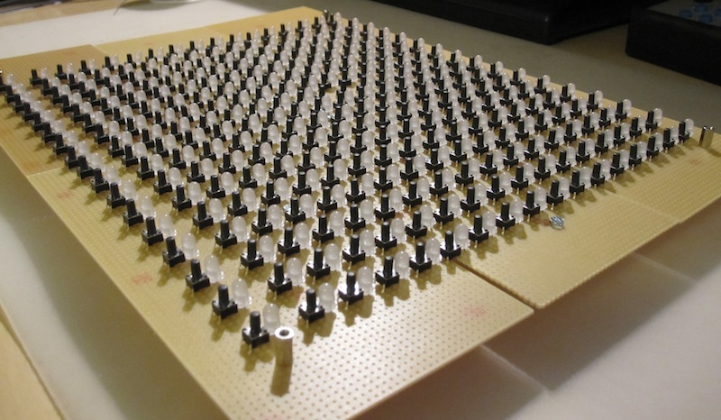
LED Matrices
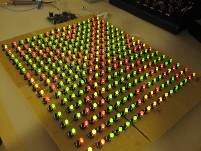
LEDs connected in a matrix allow to multiply the number of LEDs which are scanned from DOUT shiftregisters.
E.g. with two DOUT registers it's possible to scan 8x8 = 64 LEDs, with four DOUT registers (the MBHP_DOUTX4 module) even 16x16 = 256 LEDs.
MIDIbox NG supports up to 8 LED matrices, which means that up to 2048 LEDs can be serviced!
Drawback is the decreased brightness of the LEDs (the duty cycle is 1/4, 1/8 resp. 1/16 depending on the number of matrix rows). It's not a big issue for 8x8 configurations, but especially 8x16 or 16x16 configurations require LEDs with perfect mcd values, otherwise LEDs will be too dark in a bright environment!
Newbies normally prefer to connect LEDs directly to MBHP_DOUT modules. Experts prefer matrix configurations, especially if they design a dedicated PCB for their frontpanel. Good to know: it's possible to share the same DOUT shiftregister to select LED and Button matrix rows! :-)
Interconnection examples:
WS2812 based RGB LEDs
With a MBHP_CORE_STM32F4 module it's possible to drive WS2812 based RGB LEDs (usually used for LED strips) with 3x8bit resolution. The data input has to be connected to J4B.SC, ground to J4B.VS and +5V to an external PSU (required, since each RGB LED can consume up to 20 mA!)
Up to 64 RGB LEDs can be driven by the core. More could be enabled if desired by increasing the number with '#define WS2812_NUM_LEDS <number>' in the mios32_config.h file, but note that each LED will consume 48 bytes and therefore the RAM limit of the STM32F4 could be reached quickly! However, 128 LEDs are working ok so far, but this could change than more firmware features are added in future.
Rotary Encoders
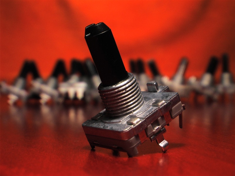
Rotary encoders (also known as "endless pots") are an attractive choise for MIDI controllers, since they allow to edit values without "parameter jumps", e.g. if they are used to access multiple parameter banks.
An encoder has two terminals (called A and B) which generate Gray encoded signals, and a common pin connected to ground. A/B are connected to two pins of the MBHP_DIN module, so that MIDIbox NG can determine the rotation direction.
Up to 128 rotary encoders can be handled by the MIDIbox NG application, non-detented and various detented types are supported.
LED Rings
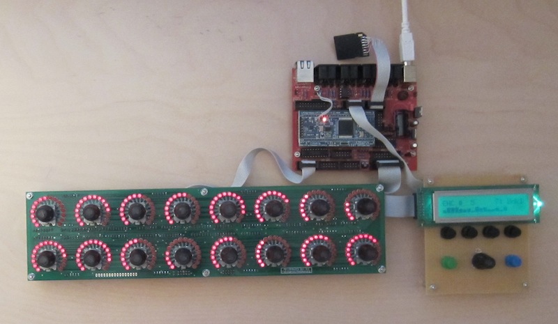
The problem with rotary encoders is the missing visual feedback of the selected value. This can be solved by displaying the value on a LCD - or with LED rings!
Especially with Fairlightiii's LRE8x2 module it was never so easy (and inexpensive) to realize Encoder/LEDring combos as before! :-)
LED Digits (7-segment displays)
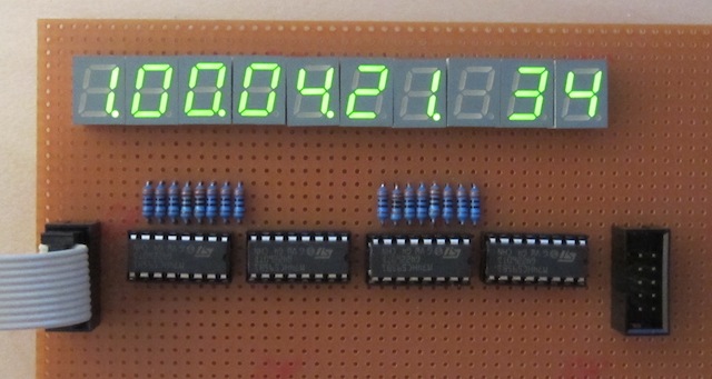
Values can also be displayed on LED Digits, regardless if they are generated from a control element (e.g. a pot or an encoder), or received via MIDI. MIDIbox NG supports 7 segment digits with common anode or cathode. Up to 5 digits can be combined to display a value (usually only 3 digits are required for a 7bit value, 5 digits for a 14bit value). Digits can also be controlled individually via MIDI, e.g. to build up a MTC display of a Logic Control Emulation (as the photo is showing).
LED Digits are organized in a LED Matrix (like LED Rings), here are some interconnection diagrams:
Pots/Faders

Many people like the direct feedback which is provided by analog pots or faders. Such components can be added by using the MBHP_AINSER64 module.
Each module allows to scan 64 pots/faders.
Up to 2 modules (= 128 pots/faders) are supported by MIDIbox NG.
Optionally MBHP_AINSER8 modules could be used as well. It doesn't come with multiplexers, is much smaller, and is therefore better suitable if only 1..8 analog inputs should be scanned.
Advantage: the tactual feel is much better compared to rotary encoders, parameters can be modified "blindly" by touching the exact position of the knob.
Disadvantage: parameter jumps if a different parameter bank is selected, or values are changed by your DAW. It's possible to overcome this drawback by using the Snap (Soft-Takeover), Relative or Parallax mode, but although they don't lead to an audible hick-up, they usually slow-down the handling of parameter changes.
IMHO the perfect MIDI controller consists of rotary encoders for parameter values which are banked, and pots/faders for values which are interactively changed while you are making music! :-)
Motorfaders

Motorfaders will move to the target position on bank or DAW changes. They are expensive! But this doesn't prevent Power-DIYers to add them to their MIDI controller - especially Mixing consoles with total recall capabilities! ;-)
MIDIbox NG allows to access up to 4 MBHP_MF_NG modules, which means that up to 32 motorfaders (and motorpots) can be controlled.
CV Outputs

Voltage Controled outputs (CV) are supported as well - they allow to convert MIDI values into analog voltages. Beside of the simple translation of 7bit based CC or 14bit NRPN/PitchBend values, MIDIbox NG even supports Note Stacks and Gate functions (available on DOUT pins) so that analog synthesizers can be played via MIDI.
Up to 4 MBHP_AOUT or 4 MBHP_AOUT_LC or 4 MBHP_AOUT_NG modules can be connected, which means that up to 32 CV channels can be controlled.
Interconnection diagrams:
Note: gates have to be connected to DOUT pins; MIDIbox NG doesn't allow to connect them to J5 pins like for other MIDIboxes (which would require additional hardware (level shifters) anyhow, since these pins only output 3.3V)
More than one LCD

MIDIbox NG provides so many different LCD options, that this topic deserves a special page: LCD Hardware Options.

Last update: 2026-03-13
Copyright © 1998-2026, Thorsten Klose. All rights reserved.
|